Integrated Cycloidal Robotic Actuator
A 19:1 cycloidal-reduction robot joint built around an Eaglepower 8308 BLDC motor — designed, 3D-printed, assembled, and characterized.
A compact, high-torque robot joint actuator integrating an Eaglepower 8308 BLDC motor with a 3D-printed 19:1 cycloidal reduction. Designed and built in January 2026 as a candidate joint for a humanoid robot, going for the combination of high torque density, smooth output, and quasi-direct-drive feel that BLDC plus cycloidal pairings can offer when done well.
CAD source on Onshape.
Design
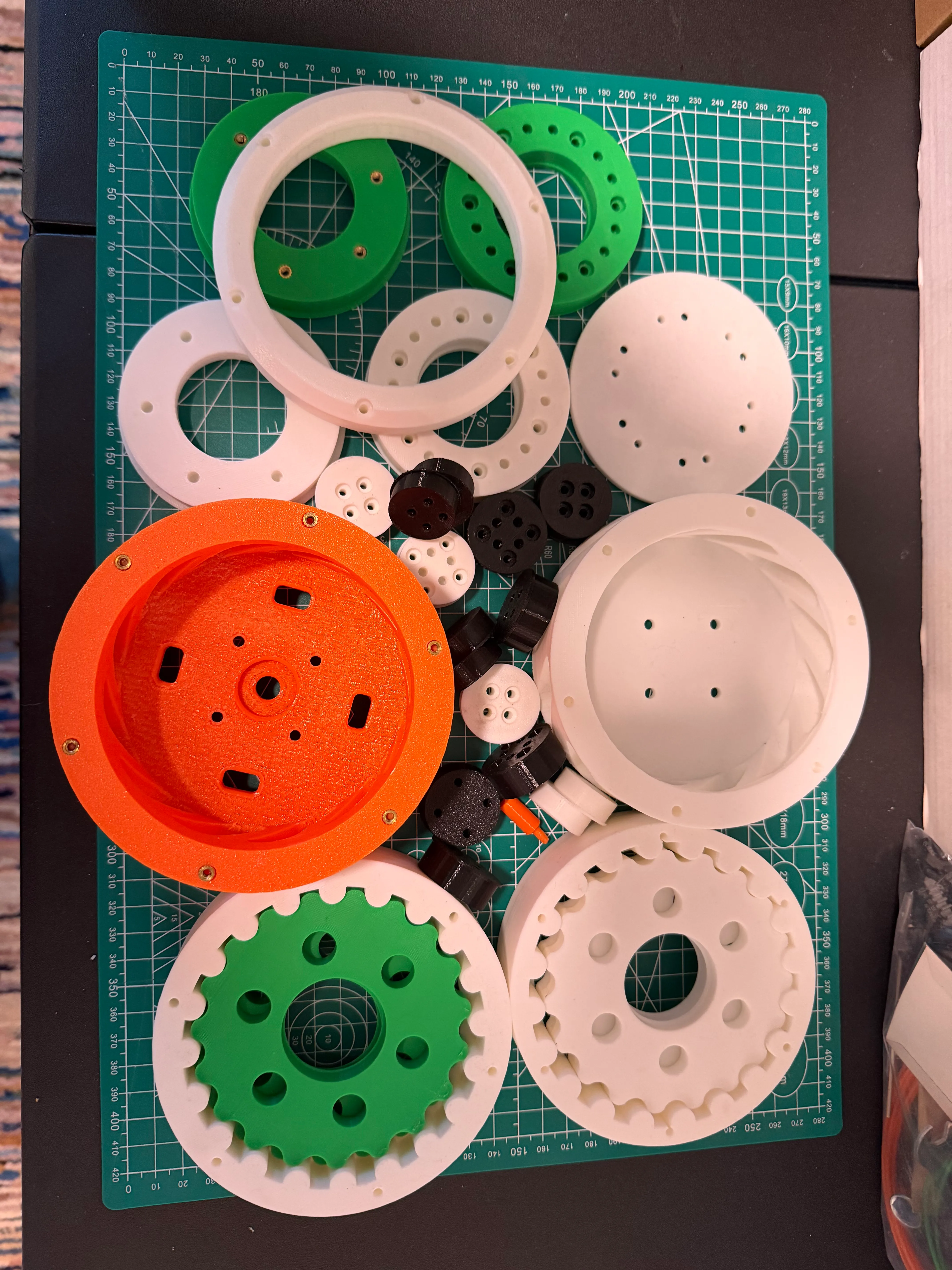
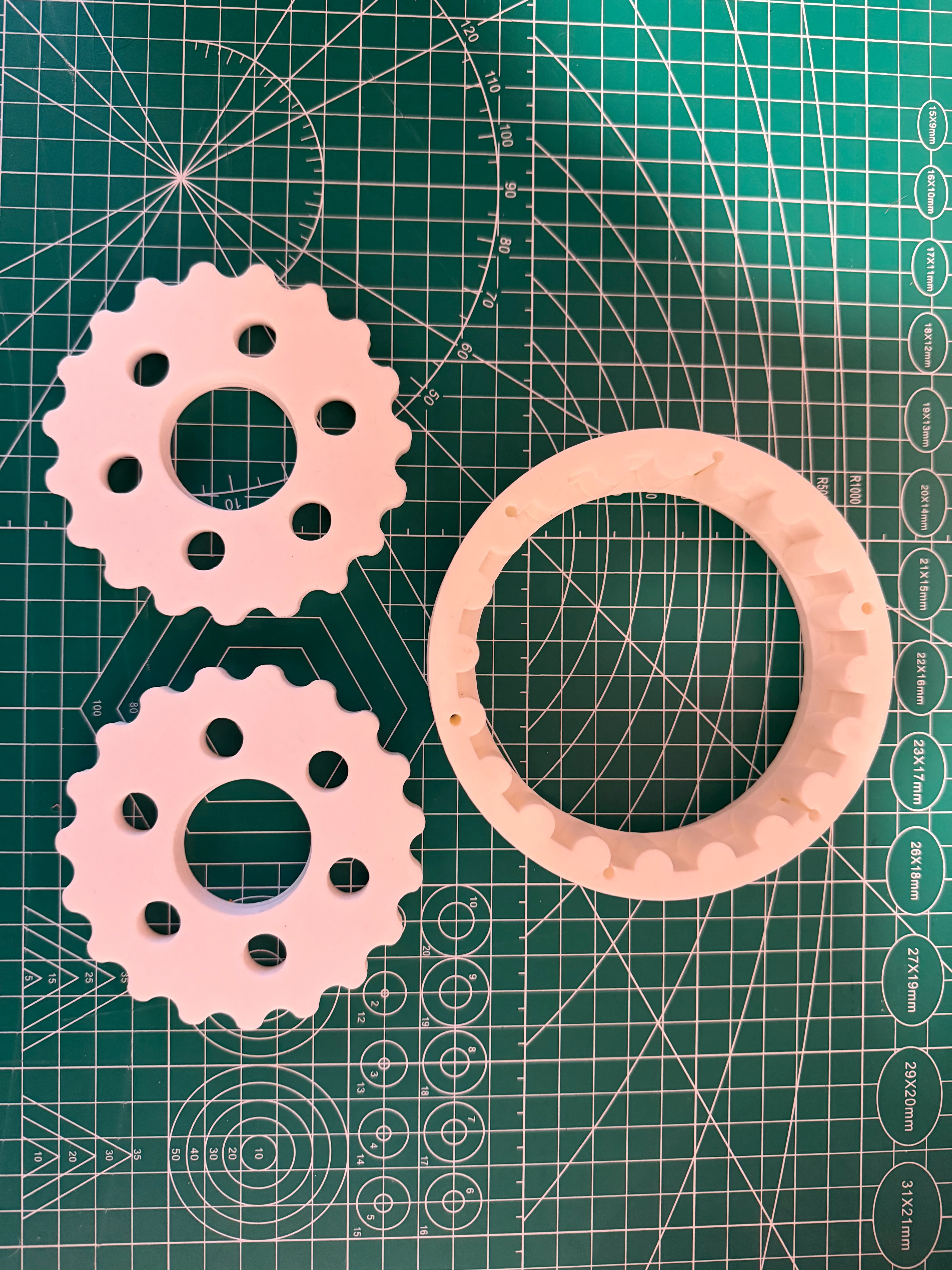
The reduction uses a pair of cycloidal discs running 180° out of phase on an eccentric cam, both rolling against a 20-lobed ring gear to produce a 19:1 ratio. Six output pins ride in matched bores through the discs and drive a common output disc. The cycloidal disc profiles started from STP files generated on mevirtuoso.com, which I then designed the surrounding actuator around.
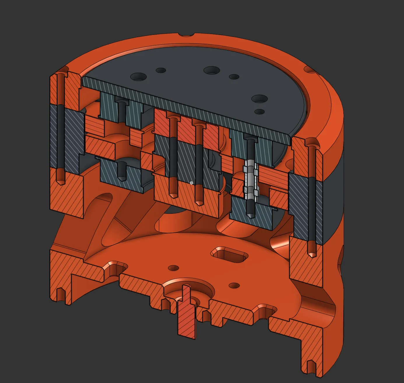
A few design choices worth calling out:
- Integrated external pins on the ring gear. The ring gear’s pin-rollers are part of the same printed body rather than separate pressed-in dowels. This simplified assembly and saved weight at the cost of being more sensitive to print quality on the lobe surfaces.
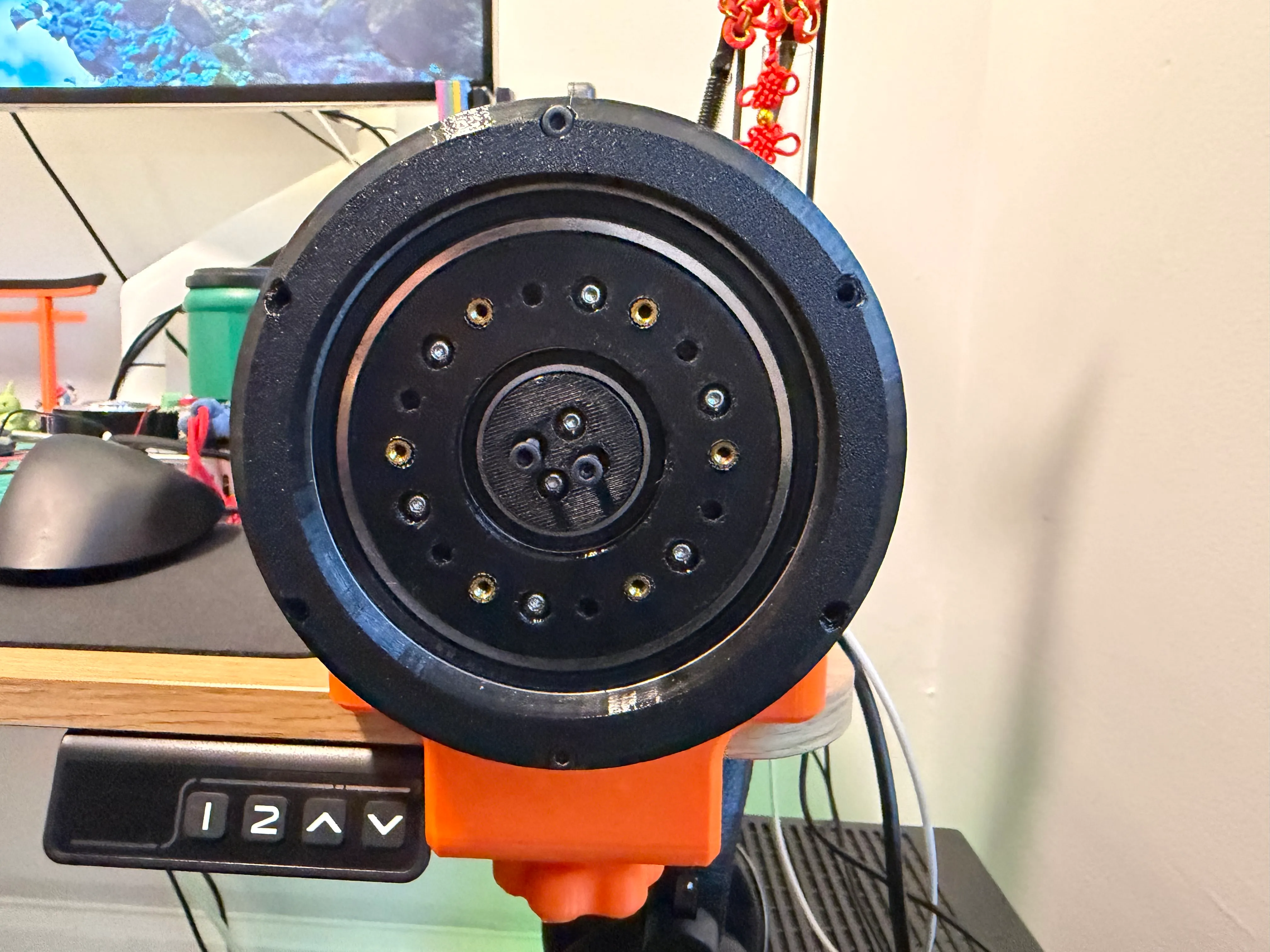
- Heated brass inserts throughout. Every fastener interface uses a heat-set insert so the actuator can be assembled and disassembled repeatedly without stripping threads in the plastic. That mattered for a part I expected to iterate on.
- Four bearing sizes, M3 hardware everywhere. The output pins each ride on a pair of small bearings (12 total), with two each of three larger sizes for the input shaft, eccentric cam, and main output. Standardizing on M3 bolts and printed spacers kept the BoM and the toolset small.
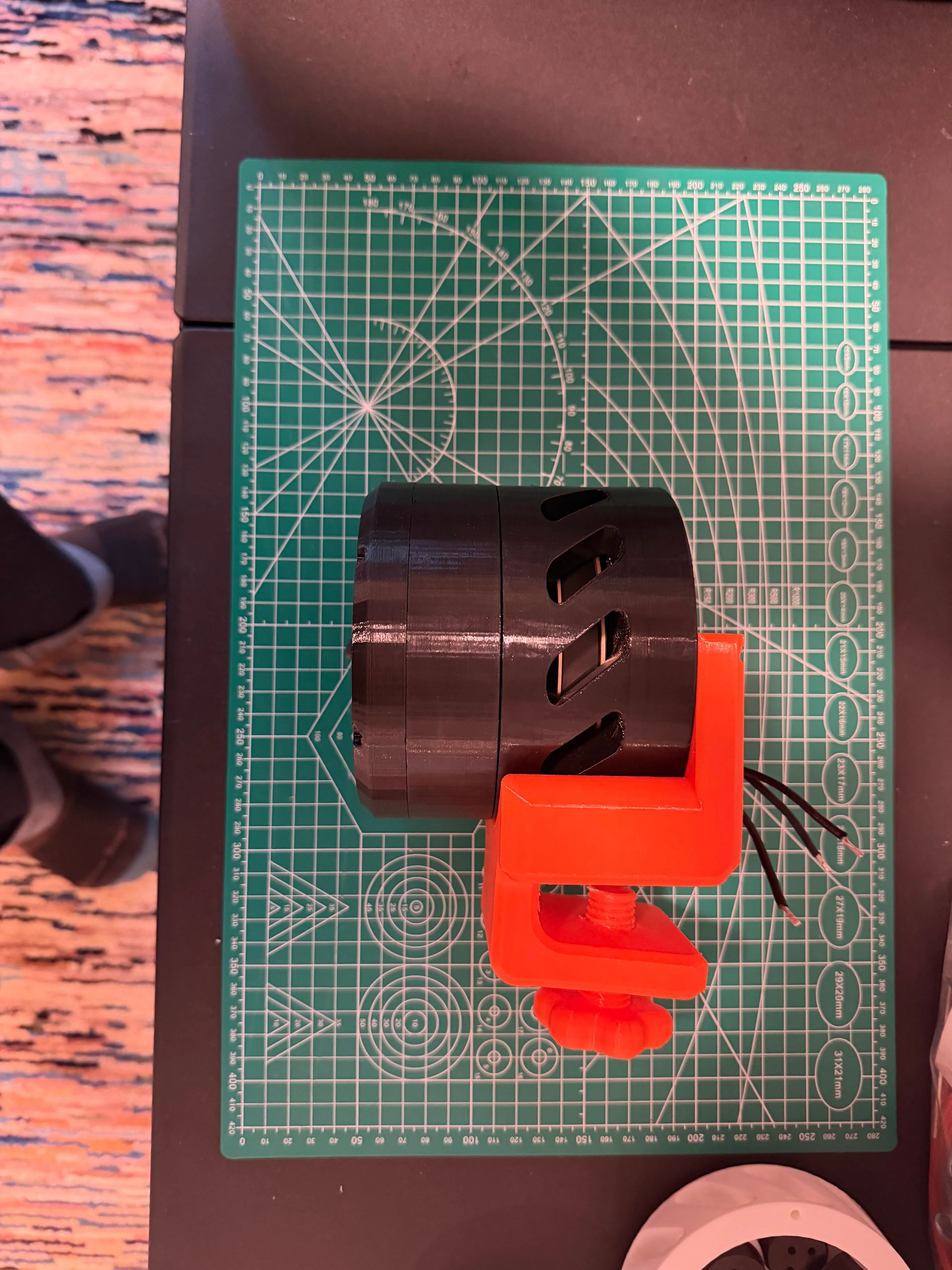
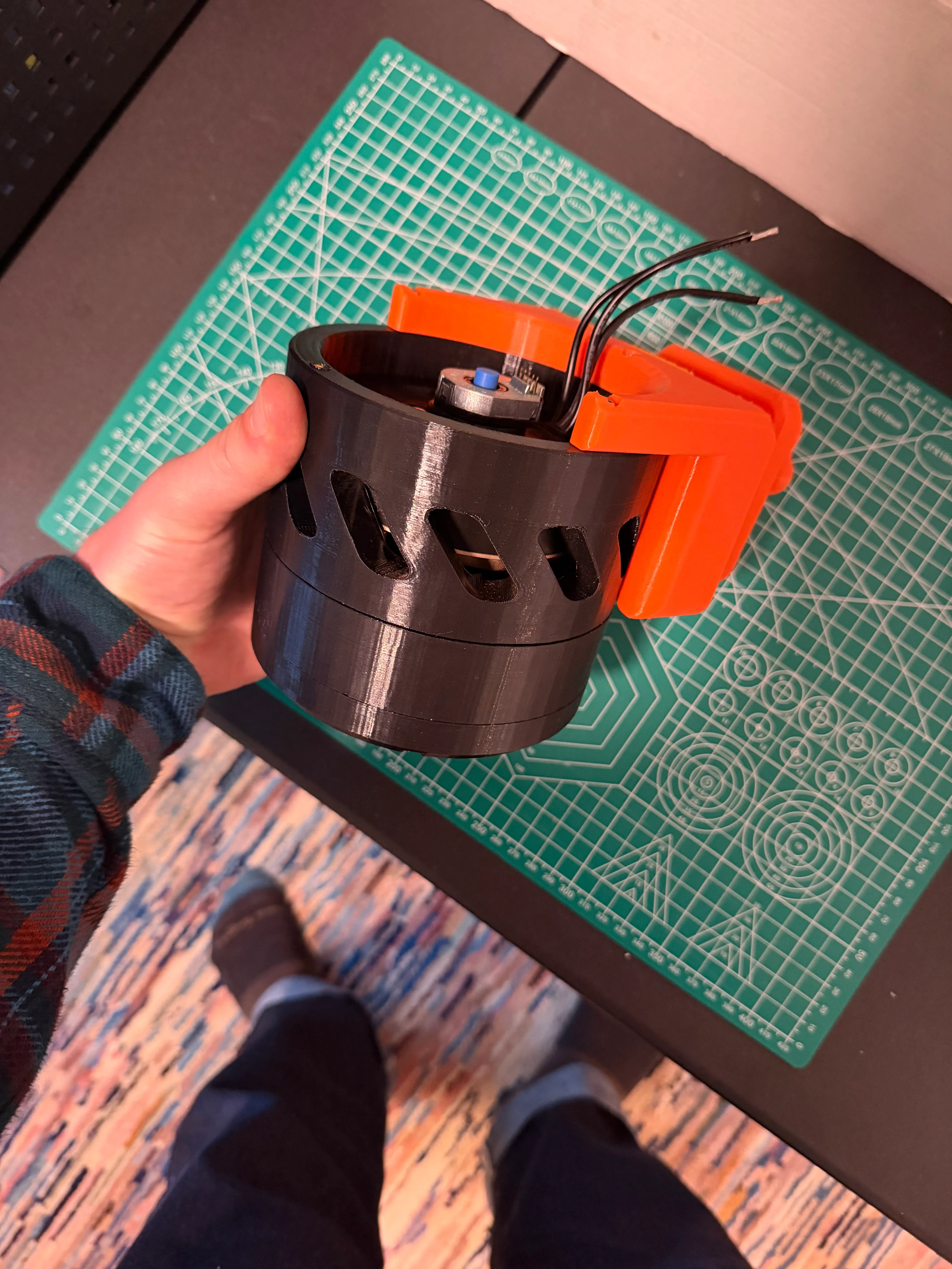
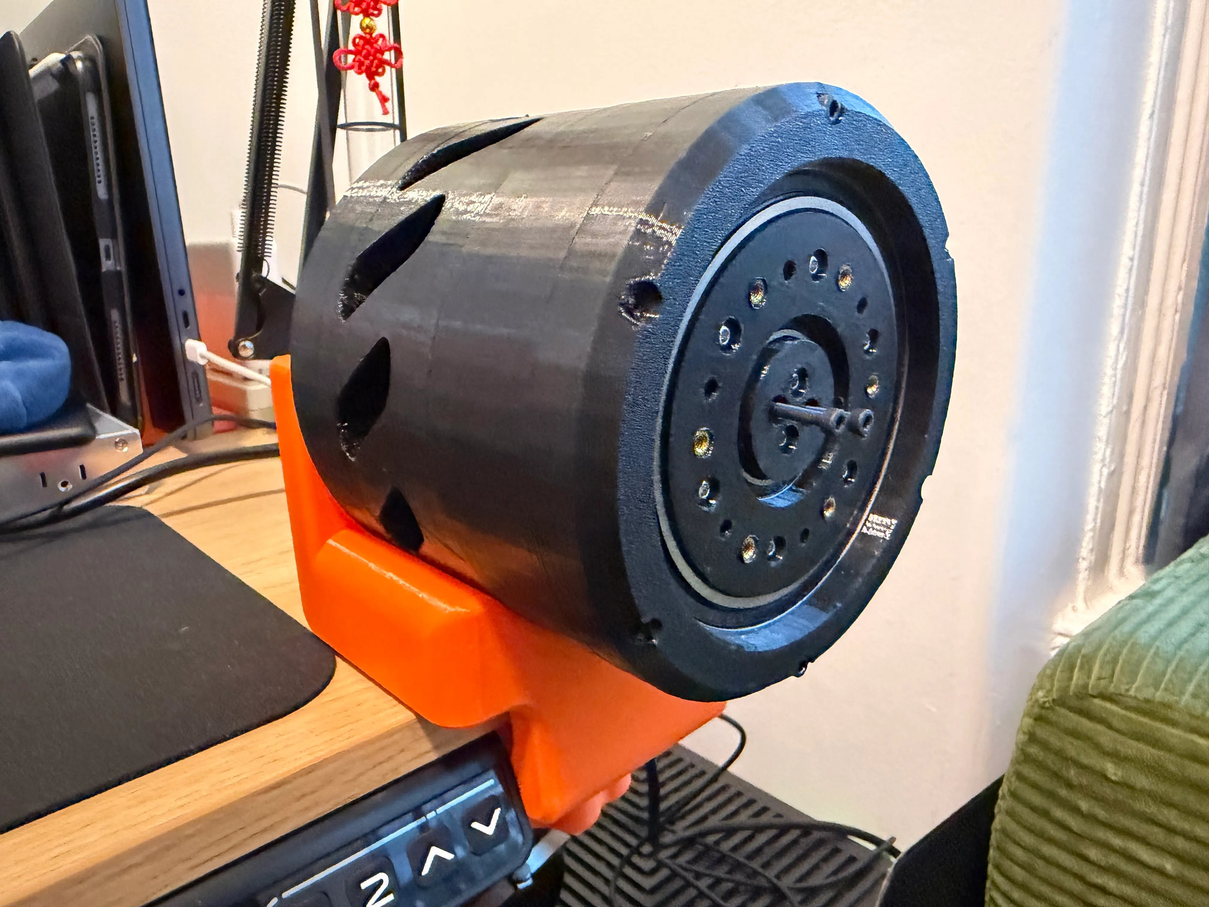
- Onshape + Bambu P1P. All CAD in Onshape; all parts printed in PETG and PLA on a Bambu P1P. The orange piece in the photos is a desk-clamp fixture I printed to hold the actuator during bench testing.
Electronics & Control
- Motor: Eaglepower 8308, a large-diameter, low-Kv outrunner intended for gimbal and robotics use.
- Controller: A Flipsky / ODESC-style FOC controller, chosen as a much cheaper alternative to a real ODrive. Getting it to behave was a significantly bigger pain than expected. The firmware is essentially abandoned, so the integration ended up being a long exercise in reverse-engineering odrivetool flags and calibration sequences against a board that didn’t quite match the docs.
- Encoder: A CUI Devices AMT103-V incremental encoder on the motor input. I considered adding a second encoder on the output for closed-loop control through the gearbox, but decided it wasn’t worth the added complexity for what I was learning.
- Tuning: I wrote Python scripts to step through calibration, set FOC gains, and run torque/speed profiles while logging current and position. Most of the practical learning on this build happened in that loop.
Performance
After assembly and tuning:
- Final-stage torque: up to ~50 Nm
- Efficiency: ~70%
- Backlash: ~2°
- Backdrivability: poor. The 19:1 ratio plus the printed geometry made the joint hard to backdrive by hand.
The 2° of backlash and the limited backdrivability were the two findings that ultimately steered me away from using this actuator in the humanoid build it was originally designed for. For a record-flipper-style or stationary arm it would be fine; for a balancing biped where compliant, backdrivable joints matter, it was the wrong tool.
Bill of Materials (rough)
| Item | Qty | Cost |
|---|---|---|
| Eaglepower 8308 BLDC motor | 1 | $80 |
| Flipsky ODESC V4.2 24V FOC controller (B0CB64MVHC) | 1 | $40 |
| CUI AMT103-V incremental encoder | 1 | $30 |
| 3×7×3 mm bearing — output pins (B0DXZKVZMR) | 12 | $15 |
| 6805-2RS bearing, 25×37×7 mm (B082PYT33D) | 2 | $15 |
| 6806-2RS bearing, 30×42×7 mm (B082PXK5K9) | 2 | $15 |
| 6816-2RS bearing, 80×100×10 mm (B07RQ4RXDR) | 2 | $15 |
| M3 hardware + brass heat-set inserts | — | ~$25 |
| PETG + PLA filament | — | ~$15 |
| White lithium grease | — | ~$5 |
| Total | ~$255 |
That cost-per-joint is the other reason the design didn’t carry forward into the humanoid: scaled across the degrees of freedom I wanted, the bearing and motor BoM alone made it impractical for a hobby-budget build.
Takeaways
- I now have a much better intuition for the geometry of cycloidal drives. The relationship between lobe count, eccentricity, and pin-output sizing is something I can sketch out from scratch.
- Printed cycloidal discs can absolutely make real torque, but ~2° of backlash is a hard ceiling for what FDM tolerances will give you without post-machining.
- Cheap “ODrive-compatible” boards are a trap when the firmware is unmaintained. For the next actuator I’d either pay for a real ODrive/MJBots controller or commit to a fully open stack like SimpleFOC from the start.
Hardware: Eaglepower 8308, Flipsky/ODESC FOC controller, magnetic encoder, ball bearings (4 sizes), M3 hardware with heat-set inserts, PETG/PLA on Bambu P1P, white lithium grease.
Software: Onshape (CAD), Python (tuning + characterization), odrivetool.
Images